DIY CNC: Building the MDF Frame
Kicking off the first real ‘build’ stage of this project, I scratched a few ideas from existing CNC projects and decided to go with a cartesian type config with a fixed gantry and moving bed. It was the simplest route with the parts I already had and in order to do this cheaply, as a proof of concept, I chose MDF.
Medium-density fibreboard (MDF) is an engineered wood product made by breaking down hardwood or softwood residuals into wood fibres, often in a defibrator, combining it with wax and a resin binder, and forming it into panels by applying high temperature and pressure. MDF is generally denser than plywood. It is made up of separated fibres, but can be used as a building material similar in application to plywood. It is stronger and much denser than particle board.[From Wiki]
I headed over to my local builder supply and purchased a sheet of MDF which they happily cut down to my required sizes for a nominal fee. I was happy to pay for straight cuts as all I had at my disposal was a hand held jigsaw. I also grabbed a square, a level, a straight edge and a steel ruler for marking and measuring.
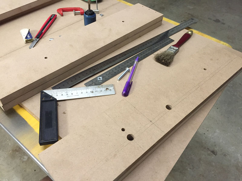


I doubled up the gantries and used the layers to countersink the 10mm stainless steel shafts which will function as the axis rails with LM10-UU Linear bearings to help the axes glide along. A Quick test fit of the lead screws and 8mm ID retainer bearings was a success and I then mounted the gantry to the base and began preparing the Y axis rails and lead screw mounts.
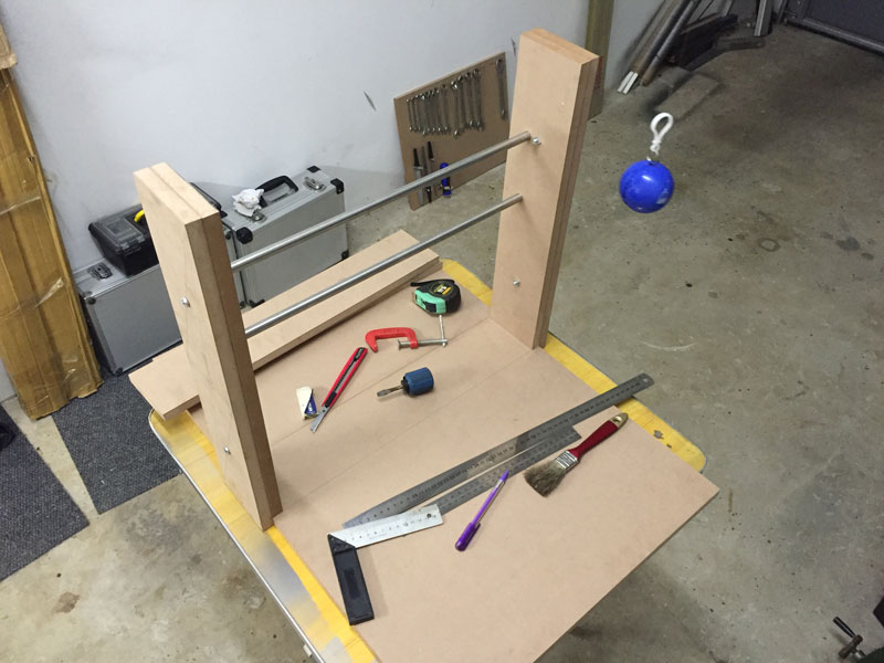
Next, I assembled the Y axis and workbed. While MDF is quite firm and feels like a solid material, Its at this point that the doubt begins creeping in. The frame feels sturdy, but it does give under some pressure. Hopefully that’s just me exerting pressure in completely the wrong directions.

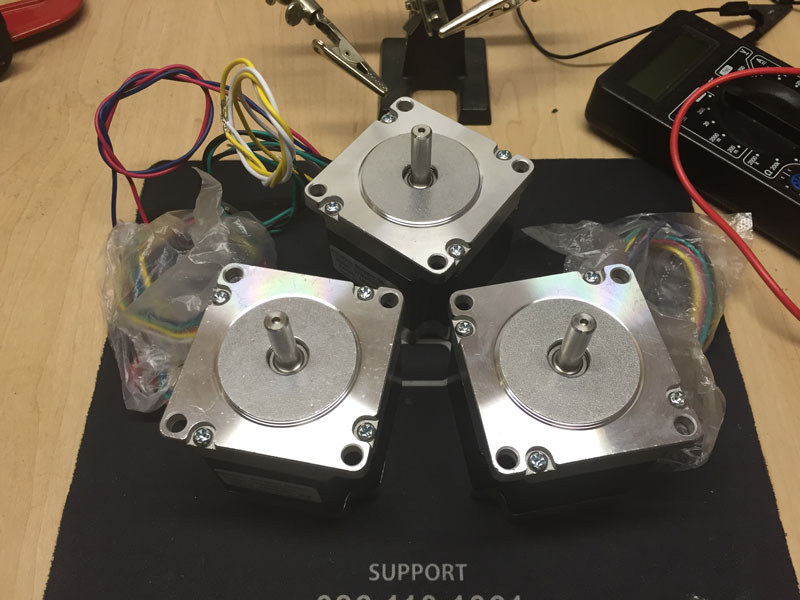
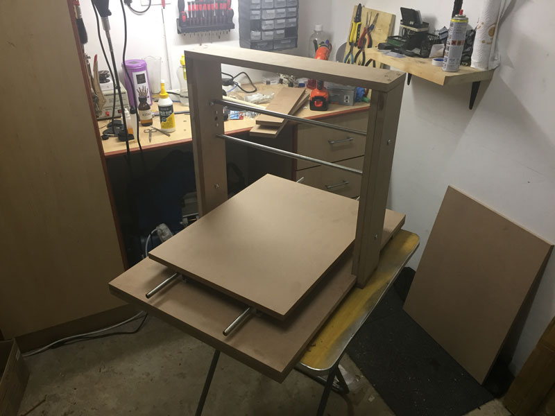
Now that the frame is assembled, we can go ahead and begin installing the rest of the parts that enable it to do it’s thing. Next up I’ll be preparing the controller and testing the electronic components before they get installed in the machine.